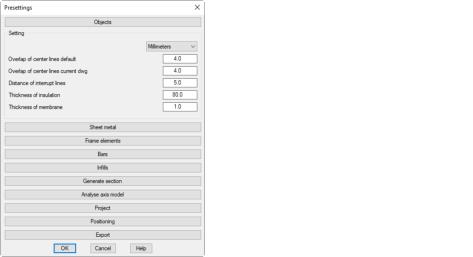
When you click on the Default settings ... button in the Dialog box ATHENA options, ATHENA starts a dialog box where you can carry out the presettings for various functions.
Dialog box Presettings
db_ath_optionen_einstellung
The dialog box contains the following drop-down menus:
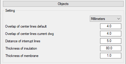
In the upper pick list you can define in which units the values of this dialog box section are displayed. You have a choice between millimeters and inches.
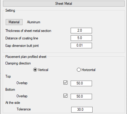
Here you determine whether the preset clamping direction is to be horizontal or vertical.
Top - Overlap Bottom - Overlap
Here you can switch the overlap on or off and set the default value for it.
At the side - Tolerance
Here you define the default values for tolerance at the side.
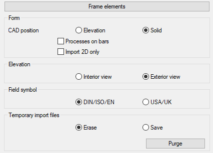
Drop-down menu Frame elements
db_ath_optionen_voreinstellung-einsatzelemente
Dialog box section Display
Here you define how CAD positions are inserted into the drawing with the command Frame element.
Elevation
Generates a CAD position as 2D view in the drawing.
Solids
Generates a CAD position as a three-dimensional solid in the drawing. This option is not available if the Import 2D information only switch has been activated.
You can subsequently change the view of the inserted CAD positions with the command Display modes.
Bar processes
Displays bar processes. This option is only available when CAD positions are inserted as solids.
Import 2D information only
Imports only 2D information of the elements. Element blocks are thus imported directly from LogiKal, which means an improvement in performance.
Switching the CAD positions to a 3D representation is not possible because the 3D information required for this is missing!
Dialog box section View
Interior view
Creates the frame element as a view from the inside.
Exterior view
Creates the frame element as a view from the outside.
Dialog box section Field symbol
DIN/ISO/EN
Opening symbols for frame elements are generated such that the opening points to the hinged side and the tip points to the handle side.
USA
Opening symbols for frame elements are generated such that the opening points to the handle side and the tip points to the hinged side.
Dialog box section Temporary import files
Remove
Temporary import files are deleted. This is the normal case.
Save
Temporary import files are saved. If there are problems during import, you can activate this setting and send the import file to Technical Support for checking.
Drop-down menu Bars
db_ath_optionen_voreinstellung-3d_staebe
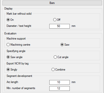
Dialog box section Mark bar without solid
Controls the marking for bars without solid (Dialog box Display modes, profile representation = axis):
• For null bars a green directional cone is displayed.
• For bars in axial representation which have not yet been assigned to any job, a green directional cone is shown.
• For bars in axial representation which have been assigned to a job, the position number is shown.
Variants of bar marking.
On
Displays the marking.
Off
Displays no marking.
Diameter/text height
Determines the absolute size of the marking.
After switching on and off or changing the size of the marking, you have to regenerate the drawing so that the change is visible.
Dialog box section Machine support
Machining center
As standard, uses the machine support, which was set for the CNC machining center (CMC), for calculating the cutting angle.
Saw
As standard, uses the machine support, which was set for the saw, for calculating the cutting angle.
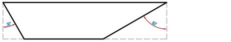
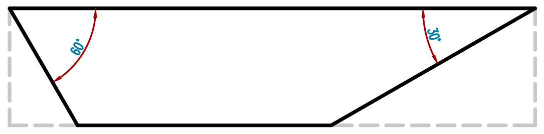
Dialog box section Specifying angle
Defines which angle is specified or dimensioned in the evaluation (lists and diagrams).
Saw angle
Specifies the angle that must be set on the saw.
Saw angle
Intersection point
Specifies the angle that can be measured on the workpiece.
Intersection point
Dialog box section Export NCW by tag
Singly
Exports each bar to a separate ncw file.
Combine
Exports all bars to a single ncw file.
Dialog box section Development segmentation
These settings affect the calculation of the development of the round tubes. The default values are suitable for tubes up to a diameter of approx. 200 mm. With larger diameters you should enlarge the arc length.
Arc length
Specifies the arc length for which a segment is inserted for segmented development.
Minimum number of segments
Specifies the minimum number of segments.
Drop-down menu Infills
db_ath_optionen_voreinstellung-3d_fuellungen
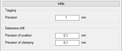
Dialog box section Tagging
This setting has an effect on the same-part recognition of infills. You will find further information on this in the section Assign tags.
Precision
Defines the accuracy for same-part recognition for infills.
The setting is primarily intended to compensate for drawing inaccuracies. For example, they can ensure that infills drawn with minimal unevenness are included in the infill list.
Dialog box section Determine infill
These settings act on the automatic infill determination. You will find further information in the section Determine infill.
Precision of position
Inaccuracies in the offset of infill positions are ignored up to the stated value. Larger inaccuracies are displayed by the message: Conflict - infill positions of boundary objects.
Precision of clamping
Inaccuracies in the clamping thicknesses of the infill positions are ignored up to the stated value. Larger inaccuracies are displayed by the message: Conflict - clamping of boundary objects.
These settings act on the section generation. You will find further information on this in the section Generating a section from 3D.
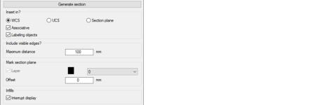
Dialog box section Insert in
WCS
Inserts the generated section in the XY plane of the World Coordinate System.
UCS
Inserts the generated section in the XY plane of the current User Coordinate System.
Section plane
Inserts the generated section in the specified sectional plane.
Associative
Generates associative sections. The section can therefore be updated for geometrical changes.
Labeling objects
Labels the sectioned objects. In the section profiles are labeled with their item number.
Dialog box section Include visible edges
Maximum distance
Specifies the maximum distance to the sectional plane in which visible edges of the solid of unsectioned bars and infills are displayed in section. E.g.: You are generating a horizontal section through two mullions. If a transom is located less than 100 mm below the sectional plane, its visible edges are shown in section.
Dialog box section Mark section plane
Layer
The tick box activates the sectional plane marking. In the pull-down menu you can select a layer for marking.
Enlarge by
Specifies the enlargement of the sectional plane marking.
The sectional plane is identified by a region. The size of the region corresponds to the enclosing rectangle of the sectioned objects plus the enlargement. With associative sections the sectional plane marking cannot be turned off.
Dialog box section Infills
Interrupt display
Generates infills with interrupted display (right and left section instead of complete infill).
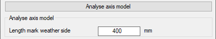
Drop-down menu Analysis of axis model
db_ath_optionen_voreinstellung-3d_achsanalyse
Length mark weather side
Specifies the length of the red lines which mark the weather side during the analysis of axis models.
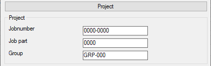
Drop-down menu Project
db_ath_optionen_voreinstellung-projekt
Job number
Defines the default designation for job numbers.
Job part
Defines the default designation for job parts.
Group
Defines the default designation for groups.
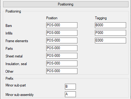
Drop-down menu Positioning
db_ath_optionen_voreinstellung_3d_positionierung
Position
Defines the position number prefixes that will be assigned to the different elements under the nickname of the project. Assigning an order with the Project browser parts from the drawing will automatically give you a position ID with the appropriate prefix. The numbers will be incremented.
Tagging
Defines the prefixes that are assigned to the individual parts in common-part identification. If you select the parts Assign tags, these numbers will be incremented. You will find further information in the section Assign tags. This specification can be adapted in the Dialog box Project Manager for each job when creating jobs.
Prefix - subordinate bar
Defines the prefix for subordinate bars (e.g. connections in the event of breaks).
Prefix - Minor sub-assembly
Defines the prefix for minor sub-assemblies (e.g. screwed joints of connections in the event of breaks).
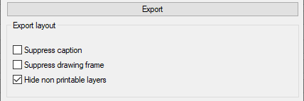
Drop-down menu Export
db_ath_optionen_voreinstellung_export
Here you define the default settings for exporting layouts to the model area of a new drawing. You will find further information on this in the section Export layout.
Suppress caption
With the tick box activated, the captions in the layout are not exported to the model area of the new drawing.
Suppress drawing frame
With the tick box activated, the drawing frames in the layout are not exported to the model area of the new drawing.
Hide non printable layers
With the tick box activated, objects that are located on layers that are suppressed during plotting are excluded from export.