Tab ATHENA Modeling > Group Data > Edit bar assembly
Menu:
Modeling > Manage > Edit bar assembly
Toolbar:
ATH Manage > Edit bar assembly
Command input:
ath_bar_edit_std
This function is used for creating and editing common bar assemblies. These can be used as a spatial 3D bar or as a section in the drawing. Common bar assemblies are, for example:
• Bar assemblies without further intelligence, i.e. those which only contain outline information.
• Bar assemblies which are formed from references. References are pointers to other bar assemblies (similar to external references in drawings). The following variants and combinations can be defined from references.
– Simple variants. Application example: Mullions with or without mullion reinforcement.
– Glazing, i.e. assemblies whose components are modified or displaced depending on the glass thickness. Application example: Transoms in which variously thick glass can be fitted.
You can create more complex bar assemblies with the Edit bar assembly (extended) command, where you have an extended range of functions.
Bar assemblies are compatible, no matter with which function they were created. There are restrictions for bar assemblies that have been created with the extended function. If these extended functions cannot be edited with the bar assembly editor, a note is displayed.
When you execute the command, the following appears:
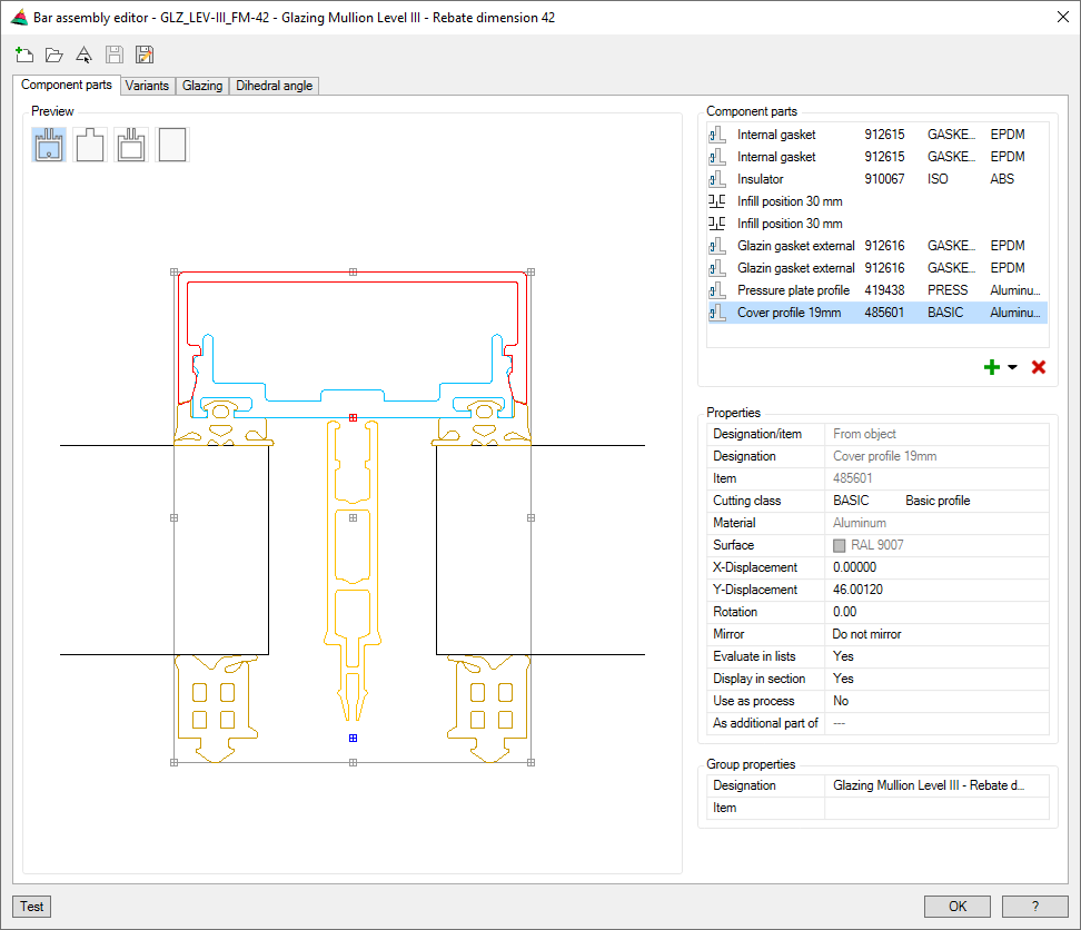
Dialog box Bar assembly editor
The designation of the current bar assembly is shown in the title row.
Below the title row there is the quick access area with important management functions.
The operating section contains the following tabs:
Brings an object from the drawing into the editor. For this, the dialog box is temporarily closed and the following appears:
Input request
Select bar assembly:
Select the bar assembly, which you want to edit in the Editor.
Save
Saves a named bar assembly without having to specify a new name. When you save an unnamed bar assembly, the Dialog box Save is displayed. You will find information on this in the section Saving objects.
Save as
Saves the bar assembly under a new name. To do this, the Dialog box Save is displayed. You will find information on this in the section Saving objects.
Display section
The display section is the same for all tabs. In the preview you can see the components of the bar assembly.
All components are displayed in the color of the respective material layer. Selected objects are highlighted in color. The highlighting is done by default in red, but can be changed in Dialog box Display options.
The display of the bar assembly in the preview can be influenced by pressing switches as follows:
Full component outline
Displays the complete component outline of all components of the bar assembly.
Cutting outline
Shows the cutting outline of the selected component of the bar assembly. If none has been defined, this corresponds to the respective external outline
Simplified outline
Displays the simplified outlines of all components of the bar assembly as a gray overlay over the component outline.
Enclosing rectangle or simplified outline
Displays the enclosing rectangle of the external outline for complex components. Internal outlines are always masked out in this display.
The simplified outline displays components of up to 16 sides. With parts with more than 16 sides or arch-shaped segments the enclosing rectangle is shown.
For outlines of standard profiles, semi-finished products and sheet metal sections, the radii are automatically straightened for the simplified form.
Operating section
Here you manage your bar assemblies and define rules for their application.
Simple bar assemblies consisting of one or more components are primarily managed in the Tab Component parts.
If you want to define variants, i.e. replace components during use, switch to Tab Variants.
Rules for bar assemblies with variable clamping thickness are defined in the Tab Glazing.
To define rules for bar assemblies whose components change depending on the dihedral angle, switch to Tab Dihedral angle.
Tab Component parts
db_ath_bar_edit_std_bauteile
This tab contains a list of components and the list of properties in the operating section.
If you select a component in the list, you can access the properties to make changes.
If you select several components by pressing the Ctrl or Shift key, you can change their properties simultaneously. Since not all properties can be changed simultaneously, the list of properties is reduced accordingly.
Further functions can be found in a context menu that appears when you click with the right mouse key.
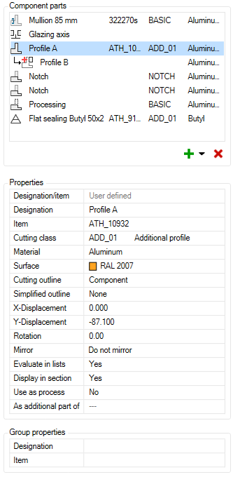
Dialog box section Component parts
The component list contains the components of the bar assembly in tabular form.
The component table has the following columns:
• Component symbol
• Designation
• Item number
• Cutting class
• Material
Meaning of the component symbols
Outline
The source of the component consists of polyline outlines. These can also be contained in a block.
The source of the component is a reference, i.e. another bar assembly.
Symbol
A component which is an infill or axis symbol.
Processing
A component with this property acts as a continuous process on the entire bar assembly.
Notch
This component acts as a notch on joining bar assemblies when creating a corresponding bar joint.
Additional part
An additional part to another part has the effect that all parts are treated as one part. This has an effect on the cutting and the evaluation.
Adding and removing components
With the icons below the list, you can add components to the bar assembly or remove selected components.
Add (from the drawing)
Creates new components from drawing objects. These can be:
• Polyline outlines
• Polyline outlines within blocks
• Cross sections of bar assemblies
• ATHENA objects (standard parts, semi-finished products, metal sheets...)
In order to select the drawing objects, the dialog box is temporarily closed and the following appears:
Input request
Specify assembly base point [?]:
Specify the base point of the bar assembly.
Select components: [?]:
Choose the components or outlines which you want to add to the bar assembly.
Further input requests may appear depending on the selected objects or outlines.
For sheet metal sections:
Select the elevation side [?]:
Specify the elevation side of the bar assembly.
For objects without a system base point:
Specify component base point [Adopt/?] <Adopt>:
You define the base point of the component. By pressing the Enter key you adopt the base point of the bar assembly.
If you specify the base point, the X and Y distance between the component and the bar assembly is taken as the X and Y displacement. If you accept the base point, the displacement is 0.
Deletes the selected components from the bar assembly.
This action is not reversible. You can only close and reopen the bar assembly without saving. However, other changes to the bar assembly are then also invalid.
Options in the Context Menu
The functions are displayed when you click a component with the right mouse key. The displayed options vary depending on the component type, so not all options are always offered in the context menu.
Display component info
Opens the Dialog box Component info, where information such as the dimensions and weight of the component can be seen.
Redefine outline
Redefines the existing outline. For this, the dialog box is temporarily closed and the following appears:
Input request
Specify assembly base point [?]:
Specify the base point of the bar assembly.
Select outlines [?]
Select the new outlines of the bar assembly.
These replace the existing component outlines.
Convert to reference
Saves the component contour as a new bar assembly and references it. The designation and item number are transferred, if available. Further data, such as name and folder, are to be specified in the Dialog box Save.
Edit reference
Opens the referenced bar assembly in the Editor.
Edit
Opens the creation dialog box for components whose source is an ATHENA object.
Dialog box section Properties
Here, you can modify the properties of the selected objects. If you have selected more than one object, only the common properties can be changed.
Designation/item
Specifies the type of component designation. The available options depend on the source of the component outline.
User defined
Is possible for the sources:
• ATHENA object (default value, can be changed)
• Polyline (value cannot be changed)
• Block (value cannot be changed)
From object
Is possible for the sources:
– ATHENA object
– Reference
Designation
Defines the component designation in several languages. You can write the designation directly into the input line in the current national language.
If you want to enter the designation in other languages, you must click the button [...]. The Dialog box Designation is opened, where you can define the designation in multiple languages.
Item
Defines the item number of a component. To do this, the Dialog box Item is opened.
The available cutting classes are listed in the pull-down menu. You can add more cutting classes in the Dialog box Cutting class when you select Edit...
The BASIC cutting class is used as the default.
You will find further information on this in the section Cutting class.
Common surfaces of the RAL Classic Palette are listed in the pull-down menu. You will find further surfaces in the Dialog box Surface manager when you click Select....
As standard, no surface is assigned. If an interface has been assigned, it can be changed as soon as you insert the bar assembly with Apply bar assembly into the drawing.
Cutting outline
Defines the cutting outline of the component. Available options are:
Component
Uses the external outline of the component as the cutting outline. This is the default setting.
Rectangle
Uses the enclosing rectangle of the component external outline as the cutting outline.
Select...
Assigns a previously drawn polyline as a user-defined cutting outline to the component. For this, the dialog box is temporarily closed and the following appears:
Input request
Specify assembly base point:
Enter the base point of the bar assembly. Once you have done that, the current cutting outline is displayed.
Select cutting outline [?]:
Select the polyline to be used as future cutting outline.
Assigns a user-defined outline to the component as a simplified outline. For this, the dialog box is temporarily closed and the following appears:
Input request
Specify assembly base point:
Enter the base point of the bar assembly. Once you have done that, the current outline is displayed.
Select simplified outline [?]:
Select the polyline which is to be used as the future simplified outline.
X-Displacement
Moves components in the X direction.
You can write the displacement value directly into the input field or specify it by clicking the button [<] in the drawing. For this, the dialog box is temporarily closed and the following appears:
Input request
Mode: Displace
Move object or [Rotate/Base point]:
Moves the component by the specified distance.
Specify the point of the movement with the mouse or select an option.
Mode: Rotate
Rotate object or [Move/Base point]:
Rotates the component by the entered angle.
Specify the rotation angle with the mouse or select an option.
Mode: Base point
Specify base point:
Defines a new base point for the Rotate or Move operations.
Specify the new base point of the arc with the mouse or select an option.
Y-Displacement
Moves components in the Y direction.
The functioning principle is identical to the X-displacement.
Rotation
Rotates components.
You can write the rotation angle directly into the input field or specify it by clicking the button [<] in the drawing. For this, the dialog box is temporarily closed and the following appears:
Input request
Mode: Rotate
Rotate object or [Base point]:
Rotates the component by the entered angle.
Specify the rotation angle with the mouse or select an option.
Mode: Base point
Specify base point:
Defines a new base point for the rotation.
Specify the new base point of the arc with the mouse or select an option.
Mirror
Mirrors components about their own system axis. Available options are:
Do not mirror
The component is not mirrored
X-Mirror
The component is mirrored in the X direction.
X- and Y-Mirror
The component is mirrored in the X and Y directions.
Y-Mirror
The component is mirrored in the Y direction.
Evaluate in lists
Defines whether the component appears in parts lists during the evaluation.
Display in section
Defines whether components are shown in section.
Use as process
Defines whether the component is to be used as a process.
If you assign a cutting class not otherwise used to the component, you can use it as a notch for joining components. Otherwise, only as a continuous process.
As additional part of
Defines the component as an additional part of another component.
In this case, the component with its additional part is regarded as one part. This also has an effect on the evaluation.
Dialog box section Group properties
Designation
Defines the assembly designation in several languages. You can write the designation directly into the input line in the current national language.
If you want to enter the designation in other languages, you must click the button [...]. The Dialog box Designation is opened, where you can define the designation in multiple languages.
Item
Defines the item number of the assembly. To do this, the Dialog box Item is opened.
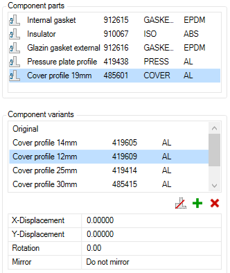
Tab Variants
db_ath_bar_edit_std_varianten
Variants can only be component alternatives that you can use when applying bars instead of the defined component. You can only assign variants to referenced components. If the bar assembly does not contain any references, this tab is deactivated and a note appears when you move the mouse over it.
Dialog box section Component parts
Lists all referenced components. Choose the component to which you want to assign variants.
Dialog box section Component variants
The list of component variants is located here, which displays the existing variants. If none have been assigned yet, only the original is in the list, which corresponds to the definition status.
Adding and removing variants
With the icons below the component list, you can add and remove variants to the selected component.
Reference can be omitted
Component may be omitted. If you click this button, the variant “Omitted” is added to the list. When applying, you can therefore decide whether the component should appear or not.
This action is not reversible. You can only close and reopen the bar assembly without saving. However, other changes to the bar assembly are then also invalid.
Once you have assigned a variant to a component, a parameter table is displayed, where you can move, rotate and mirror the variant. The function of the position parameters is identical to those of the Components tab.
The position parameters only affect the variant and not the original.
Pay attention to the preview here, where you can see the original part and the selected variant (in red).
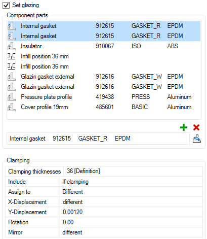
Tab Glazing
db_ath_bar_edit_std_verglasung
Here, you can define a bar assembly as glazing. A glazing is a bar assembly which clamps infills and whose parameters change depending on the infill thickness. E.g.: If the clamping increases, the inner seals are replaced or the cover is pushed outwards.
Prerequisites for defining glazing are:
• The bar assembly must include at least one Infill position.
• Visible components of the bar assembly must be references.
If these prerequisites are not met, the Glazing tab is inactive.
Set glazing
Activate the tick box to set up glazing.
The defined clamping thickness is taken from the infill position and the component parts and clamping lists are activated. You can now define further clamping thicknesses.
Dialog box section Component parts
Component list
Lists the components of the bar assembly. Here, select one or more components to manipulate them for other clamping thicknesses (replace, move, etc.). The manipulation is carried out in the Clamping dialog box section.
Removes selected components for the current clamping from the bar assembly.
Replace
Replaces selected components for the current clamping. For example, you would like to replace the defined 13 mm inner seal with an 11 mm inner seal at the current clamping.
Here you define the clamping thicknesses and parameters (e.g. displacement) of individual components.
Clamping thicknesses
Lists the originally defined and additional clamping thicknesses and provides options for adding clamping thicknesses.
Available options are:
Clamping thicknesses
Select a clamping thickness to change further parameters for the selected components.
Add...
Adds one or more clamping thicknesses. For this, the Dialog box Clamping thicknesses is opened, where you can specify the smallest and largest clamping as well as the gradient. After closing the dialog box, these are added to the list.
Add and move selected...
Adds one or more clamping thicknesses and moves selected components. For this, the Dialog box Clamping thicknesses is opened, where you can specify the smallest and largest clamping as well as the gradient. After closing the dialog box, these are added to the list and the selected components are displaced by the delta value of the clamping.
The direction of displacement is based on the component selection as follows:
• If the infill positions are part of the selection, the dimensional change of the clamping thicknesses and the displacement of the selected components takes place above the infills.
• If the infill positions are not part of the selection, the dimensional change of the clamping thicknesses and the displacement of the selected components takes place below the infills.
Remove
Removes the clamping thickness from the list.
Include
Defines how selected components are used for clamping. Possible options are:
No
Selected components are not included.
Always
Selected components are always included.
If clamping
Selected components are only included on the side of the clamping.
Assign to
Defines the assignment of the selected components to a side. Possible options are:
No
No assignment is made.
Left
Components are assigned to the left clamping section.
Right
Components are assigned to the left clamping section.
X-Displacement
Moves components in the X direction.
You can write the displacement value directly into the input field or specify it by clicking the button [<] in the drawing. For this, the dialog box is temporarily closed and the following appears:
Input request
Mode: Displace
Move object or [Rotate/Base point]:
Moves the component by the specified distance.
Specify the point of the movement with the mouse or select an option.
Mode: Rotate
Rotate object or [Move/Base point]:
Rotates the component by the entered angle.
Specify the rotation angle with the mouse or select an option.
Mode: Base point
Specify base point:
Defines a new base point for the Rotate or Move operations.
Specify the new base point of the arc with the mouse or select an option.
Y-Displacement
Moves components in the Y direction.
The functioning principle is identical to the X-displacement.
Rotation
Rotates components.
You can write the rotation angle directly into the input field or specify it by clicking the button [<] in the drawing. For this, the dialog box is temporarily closed and the following appears:
Input request
Mode: Rotate
Rotate object or [Base point]:
Rotates the component by the entered angle.
Specify the rotation angle with the mouse or select an option.
Mode: Base point
Specify base point:
Defines a new base point for the rotation.
Specify the new base point of the arc with the mouse or select an option.
Mirror
Mirrors components about their own system axis. Available options are:
Do not mirror
The component is not mirrored
X-Mirror
The component is mirrored in the X direction.
X- and Y-Mirror
The component is mirrored in the X and Y directions.
Y-Mirror
The component is mirrored in the Y direction.
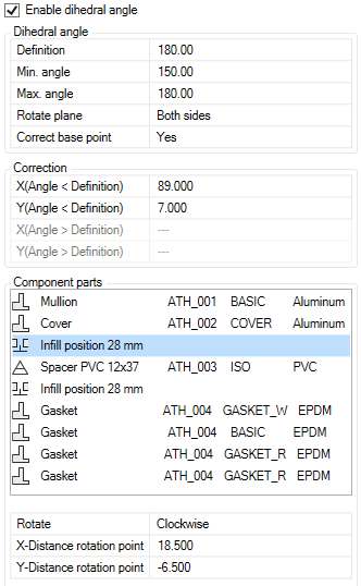
Tab Dihedral angle
db_ath_bar_edit_std_flaechenwinkel
Here, you can define a bar assembly with a variable dihedral angle. Such bar assemblies behave parametrically when the dihedral angle changes. For example, components can be displaced (by correcting the base point) or rotated depending on the angle of the adjacent surfaces.
Enable dihedral angle
Activate the tick box to define variable dihedral angles.
Dialog box section Dihedral angle
Definition
Defines the current dihedral angle of the bar assembly. In most cases the angle of definition is 180°.
Min. angle
Defines the smallest angle the bar assembly is intended to cover.
Max. angle
Defines the largest angle the bar assembly is intended to cover.
Rotate plane
Specifies which planes are to be rotated around in the event of changes in the dihedral angle. Possible options are:
Left
Rotates only the left plane by the corresponding angle.
Right
Rotates only the right plane by the corresponding angle.
Both sides
Rotates both the left and right planes by half the angle.
Correct base point
Corrects the base point of the bar assembly depending on the dihedral angle. Possible options are:
Yes
The base point is corrected and the components of the bar assembly are displaced by the correction value.
No
The base point is not corrected. No displacement of the components takes place.
Dialog box section Correction
Here you enter the correction values for the angle-dependent displacement of the base point. If the min. or max. angle corresponds to the angle of definition, only two of the four fields are active.
The correction values are dependent on the construction of the bar assembly and the specifications of the profiler. The distance from the rotation point of the component to the base point of the bar assembly has proven successful.
If this does not lead to the desired result, you must use the trial and error method to get to the right point.
X (Angle < Definition)
Defines the correction value for the X axis at angles smaller than the angle of definition.
Y (Angle < Definition)
Defines the correction value for the Y axis at angles smaller than the angle of definition.
X (Angle > Definition)
Defines the correction value for the X axis at angles greater than the angle of definition.
Y (Angle > Definition)
Defines the correction value for the Y axis at angles greater than the angle of definition.
Dialog box section Component parts
Component list
In the component parts list, you can select the components which are to be rotated depending on the angle.
Rotation
Here you define whether selected components are to be rotated. Possible options are:
None
Selected components are not rotated.
Counter clockwise
Selected components are rotated counter clockwise.
Clockwise
Selected components are rotated clockwise.
X-Distance rotation point
Defines the X distance from the base point of the bar assembly to the rotation point.
Y-Distance rotation point
Defines the Y distance from the base point of the bar assembly to the rotation point.
End of program
Test
Inserts a cross section of the bar assembly incl. cutting outline into the drawing. For this, the dialog box is temporarily closed and the following appears:
Input request
Specify insertion point:
Define the insertion point of the cross section.
Specify rotation angle <0>
Specify the rotation angle of the cross section.
OK
Closes the dialog box. If the bar assembly has not been saved, you will be asked to do so.
The content of the bar assembly editor is in any case retained for the duration of the drawing session.
Cancel
If the dialog box closes, all changes are discarded.