This function is used for creating and editing common assemblies. These can be used as a spatial 3D part or as a 2D projection directly in the drawing. With Apply arrangement, an assembly can be connected with abar by using rules. Common assemblies are, for example:
• T-connectors
• Substructures for facades
• Anchor plates
When you execute the command, a dialog box is opened in which you can create and edit assemblies.
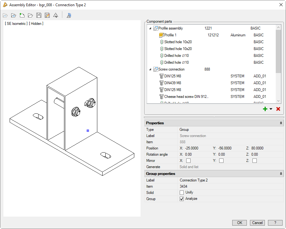
Dialog box Assembly editor
The designation of the current assembly is shown in the title row.
Below the title row there is the quick access area with important management functions.
On the left side you can see the display section with the preview.
On the right there is the operating section with the components list and fields for changing the properties.
db_ath_bgr_edir_std
Quick access area
Open previous
Opens the previous assembly in the opening sequence.
Open next
Opens the next assembly in the opening sequence.
New
Creates a new assembly. If the current assembly has been changed, you will first be asked to save it.
Brings an object from the drawing into the editor. For this, the dialog box is temporarily closed and the following appears:
Input request
Select assembly:
Select the assembly which you want to edit in the Editor.
Save
Saves a named assembly without having to specify a new name. If an unknown assembly is selected, the Dialog box Save is displayed. You will find information on this in the section Saving objects.
Save as
Saves the assembly under a new name. To do this, the Dialog box Save is displayed. You will find information on this in the section Saving objects.
Insert test assembly into drawing
Inserts the assembly into the drawing to test its functionality. The following procedure is used:
Input request
Insert assembly [projection/solid] <Solid>: With the option Solid (default), the assembly is inserted as a 3D solid. Select the Projection option to insert a 2D projection of the current display into the drawing.
Specify insertion point or [?]: Specify the insertion point of the assembly.
Specify rotation angle or [?] <0>:
Specify the rotation angle of the assembly.
With the option ? you call the help.
Since the test assembly is inserted into the drawing unnamed, this method should really only be used for test purposes. For example, test assemblies cannot be updated.
Use the Apply assembly command to insert named assemblies with all their possibilities into the drawing.
Display section
The preview is located in the display section.
The preview of the assembly can be adjusted using flyout menus as follows:
View control
Here you control the view of the assembly. You will find further information on this in the section Object views.
The view control also influences the insertion of the projection of a test assembly into the drawing.
Wire frame view type
In this mode, all components are displayed without considering their operating method.
All components are displayed in the color of the respective material layer. Selected objects are highlighted in color. The highlighting is done by default in red, but can be changed in Dialog box Display options.
Hidden view type
In the hidden display, the operating methods are taken into consideration.
The display in this mode is monochrome.
Operating section
In the operating section you can see the component list as well as lists with different properties.
If you select a component in the list, you can access the properties to make changes.
If you select several components by pressing the Ctrl or Shift key, you can change their properties simultaneously. Since not all properties can be changed simultaneously, the list of properties is reduced accordingly.
Further functions can be found in a context menu that appears when you click with the right mouse key.
Dialog box section Component parts
The component list contains the components of the assembly in tabular form.
The component table has the following columns:
• Component symbol of the object type
• Designation
• Item number
• Material
• Cutting class
Adding and removing components
With the icons below the list, you can add components to the assembly or remove selected components.
Add (from the drawing)
Creates new components from drawing objects. These can be:
• Circles, closed polyline outlines, standard profiles (these outlines are extruded with the height -5).
In order to select the drawing objects, the dialog box is temporarily closed and the following appears:
Input request
Select components [?]:
Choose the components or outlines which you want to add to the assembly.
Specify assembly base point [?]:
You determine the base point of the assembly.
You can also create components without having previously saved them in the drawing. To do this, press the arrow next to the plus and select the component type.
Component types
Extrusion
Creates a rectangular extrusion with the dimensions 100 x 50 x -5. You can subsequently adjust the dimensions and other properties.
Creates a compound part. This is the reference to an existing assembly. The operations (None, Unify, Difference, Intersection) are executed within the part.
Group
Creates a group. This is the reference to an existing assembly.
All parts of the referenced assembly are incorporated into the existing assembly before operations (None, Unify, Difference, Intersection) are executed.
Drop-down menu Properties
Type
Changes the component type. For available types, see section Component types above.
Designation
Defines the component designation in several languages. You can write the designation directly into the input line in the current national language.
If you want to enter the designation in other languages, you must click the button [...]. The Dialog box Designation is opened, where you can define the designation in multiple languages.
With most object types, the designation is transferred from the object. In this case, it cannot be changed at this point.
Item
Defines the item number of a component. To do this, the Dialog box Item is opened.
Cutting class
Defines the cutting class of a component.
The available cutting classes are listed in the pull-down menu. You can add more cutting classes in the Dialog box Cutting class when you select Edit...
The BASIC cutting class is used as the default.
You will find further information on this in the section Cutting class.
You can write the displacement value directly into the respective input field or determine it by clicking the button [<] in the drawing. For this, the dialog box is temporarily closed and the following appears:
Input request
Move the object or [Rotate/Mirror/Align/Base Point/UCS/OSnapZOff]:
Moves the component by the specified distance.
Specify the point of the movement with the mouse or select an option.
Option Rotate
Rotate object or [Move/Mirror/Align/Base Point/BaseAngle/UCS]:
Rotates the component by the entered angle.
Specify the rotation angle with the mouse or select an option.
Base angle option
Specify base angle or [UCS]:
Specify a new base angle for rotation or select an option.
Option Mirror
Specify first point of mirror line or [Move/Rotate/Align/UCS/OSnapZOff]:
Specify the first point of mirror line or select an option.
Specify the second point of mirror line or [Move/Rotate/Rotate/Align/ UCS]:
Specify the second point of mirror line or select an option.
Once you have determined the second point, the component is mirrored.
Align option Reorients the component by specifying several starting points and target points.
Define first starting point or [Move/Rotate/Mirror/UCS/OSnapZOff]:
Enter the first starting point or select an option.
Define the first target point or [Move/Rotate/Mirror/Align/UCS/OSnapZOff]:
Enter the first target point or select an option.
Define the second starting point or [Move/Rotate/Mirror/Align/UCS/OSnapZOff]:
Enter the second starting point or select an option.
Define the second target point or [Move/Rotate/Mirror/Align/UCS/OSnapZOff]:
Enter the second target point or select an option.
Define the third starting point or [Move/Rotate/Mirror/Align/UCS]:
Enter the third starting point or select an option.
Define the third target point or [Move/Rotate/Mirror/Align/UCS]:
Enter the third target point or select an option.
Base point option
Specify the base point or [UCS/OSnapZOff]:
Define a new base point or select an option.
UCS option
Specify origin of new UCS or [Area/Named/Object/Previous/View/World/X/Y/Z/ZAxis] <World>:
Specifies a new user coordinate system. You will find further information on this subject in the AutoCAD help.
OSnapZOff/OSnapZOn option
Switches the OSnap of the Z plane off or on. A respective message appears.
OSnap Z is disabled
You can move the component in all three planes.
OSnap Z is enabled
You can only move the component in the X-Y plane.
All options are repeated. Press the Enter key to complete the position change and return to the dialog box.
Rotation angle
Rotates components.
You can write the rotation angle directly into the input field or specify it by clicking the button [<] in the drawing. For this, the dialog box is temporarily closed and the following appears:
Input request
Rotate object or [Move/Mirror/Align/Base Point/BaseAngle/UCS]:
The options are identical to those of the position change.
Mirror
Mirrors components in the X, Y or Z directions.
Operation
Here you define the effect of the components.
Depending on the component type, operating methods are specified. For example, drilled holes are used as the difference as standard.
• None Does not perform any component operation.
• Union Combines components by addition.
• Difference Uses components as voids.
• Intersection Forms the intersection with overlapping components.
Generate
Controls the generation of components.
• Do not generate The component is not generated as solid and is not evaluated in lists.
• List only The component is evaluated in lists but not generated as solid.
• Solid only The component is generated as solid but not evaluated in lists.
• Solid and list The component is generated as solid and evaluated in lists.
Drop-down menu Special features
The special features are only available with extrusions.
Region
Defines the extrusion source. Available:
• User defined Uses a user-defined outline from the drawing. For this, the dialog box is temporarily closed and the following appears:
Input request
Select outlines [?]:
Use the mouse to select the outlines for the component. Internal outlines are automatically used as a difference for surrounding outlines.
Specify component base point [?]:
You define the base point of the component.
With the option ? you call the help.
• Standard Part Uses the outline of a standard profile for extrusion. For this, the Dialog box Standard Parts is opened. There you can select the desired standard profile.
• Semi-finished product Uses the outline of a semi-finished product for extrusion. For this, the Dialog box Semi-finished product is opened. There you can define the desired semi-finished product.
• Gasket Uses the outline of a gasket for extrusion. For this, the Dialog box Gasket properties is opened. There you can define the desired gasket.
• Spacer Uses the outline of a spacer for extrusion. For this, the Dialog box Spacer properties is opened. There you can define the desired spacer.
• Outline Uses an outline for extrusion. For this, the Dialog box Outline is opened. There you can define the desired outline.
Length
Defines the extrusion length of the component
Taper
Defines an angle for the taper of the component.
Drop-down menu Group properties
Designation
Defines the assembly designation in several languages. You can write the designation directly into the input line in the current national language.
If you want to enter the designation in other languages, you must click the button [...]. The Dialog box Designation is opened, where you can define the designation in multiple languages.
Item
Defines the item number of the assembly. To do this, the Dialog box Item is opened.
Unify solids
When you activate the tick box, all operations of the parts are executed. The assembly is treated as one part.
Evaluate group
If you deactivate this tick box, the assembly is not taken into account in evaluations, e.g. in lists.
End of program
OK
Closes the dialog box. If you have made changes, you will be asked to save the assembly. Even if you do not save the assembly, the last status will be retained in the dialog box.