Tab ATHENA Modeling > Group Orientation > Break bar
Menu:
Modeling > Apply > Break bar
Toolbar:
ATH Apply > Break bar
Command input:
ath_bar_break
Use this function to break a bar or a bar projection into several parts at points to be specified.
You can specify a gap dimension for the break. In addition, you can define connector elements that optionally ensure that the parts are processed (e.g. drilled holes). Example: Sheet metal cover with bumper plate, which is riveted or screwed.
Breaking bars automatically creates a structure of main parts, connectors and accessories. These parts are best evaluated in a Structured list.
When you execute the command, the following appears:
Input request
Select bar for breaking:
Select a bar or bar projection to break.
After you have selected a bar, there are other options that depend on the selected bar or whether it already has breaks or not.
These options are displayed until you terminate the command with eXit.
Add
Specify break point or [?]:
Enter a point near the bar to break it. It makes sense to mark the point in advance with auxiliary lines or similar markings.
The break is marked with a temporary red line running perpendicular to the bar direction.
This input request is repeated until you terminate it by pressing the Enter key.
Remove
Deletes the current break.
Next
Changes to the next break.
Previous
Changes to the previous break.
Details
Opens the Dialog box Bar break, where you can adjust further settings, such as the gap dimension and the joint.
eXit
Terminates the command.
A change between the breaks is necessary in order to remove them. Since it has not been possible up till now to move the break, these must be removed and added again.
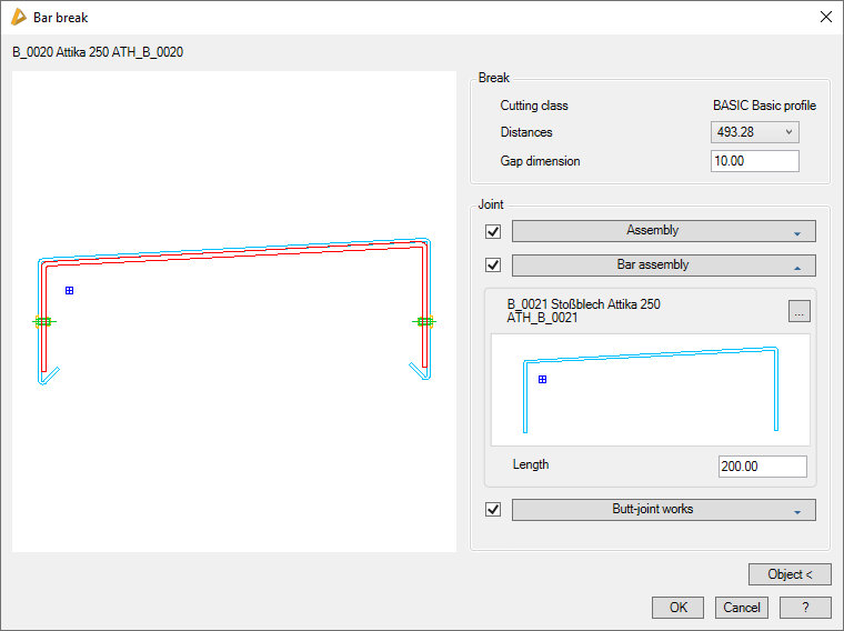
Dialog box Bar break
db_ath_bar_break
Preview
On the left you can see the preview of the break.
Dialog box section Break
Cutting class
Displays the cutting class of the bar as information.
Distances
Displays the break distances from the bar starting point as information
Gap dimension
Defines the gap dimension for all bar breaks.
Dialog box section Connection
Assembly
Defines the connector assembly.
Bar assembly
Defines the connector bar assembly.
Length
Defines the length of the connector bar assembly.
Connector processes
Defines the assembly for processing the connector, for example drilling holes.
Object <
Adopts settings for the break from another identical bar. For this, the dialog box is temporarily closed and you are asked to select a bar in the drawing.
End of program
OK applies the settings made. With Cancel you discard the settings made. In both cases the dialog box is terminated and the input request is restored.