Tab ATHENA > Group Drawing > Sheet metal section projections
Menu:
ATHENA > Sheet metal > Sheet metal section projections
Toolbar:
ATH Sheet metal > Sheet metal section projections
Command input:
ath_sheet_pr
Manages sheet metal sections to create them in different views. The sheet metal sections to be managed must be selected beforehand in the drawing.
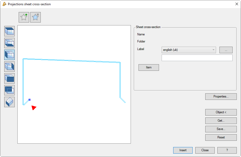
Dialog box Sheet metal section projections
db_ath_sheet_pr
Display section
At the top left there are two buttons for favorites. You will find further information on this in the section Saving and using favorites.
The preview is primarily intended for visual checks and shows the sheet metal section with the set properties. The red triangle indicates the elevation side of the metal sheet.
Furthermore, the preview offers these functions:
Additional functions are activated by clicking in the preview with the mouse wheel. You will find further information on this in the section Object preview.
To the left of the preview there are buttons with which you can adjust both the preview and also the insertion into the drawing. You will find further information on this in the section Object views.
Administration section
The following functions in this dialog box are only available when managing sheet section projections:
Properties...
Opens the Dialog box Sheet metal section. Here, you can adapt sheet properties to the geometry, such as sheet thickness, material, etc.
Object <
Adopts a sheet metal section from the drawing. This will temporarily close the dialog box and then follows:
Input request
Select sheet metal section:
Select the sheet metal section which you want to adopt.
If the cross section has already been projected, it already has a base point which you can change. For this, a dialog query appears.
When you redefine the base point, the following appears:
Specify base point or [Adopt] <Adopt>:
Use the mouse or enter coordinates to specify the base point or press the Enter key to adopt the suggested base point.