Thus, you can analyze the elements of the facade element and generate sections.
The fundamental dimensions and center distances of the facade element are defined in Dialog box Facade element. You will find further information on this in the section Facade element.
Dialog box Facade element+
db_ath_front+
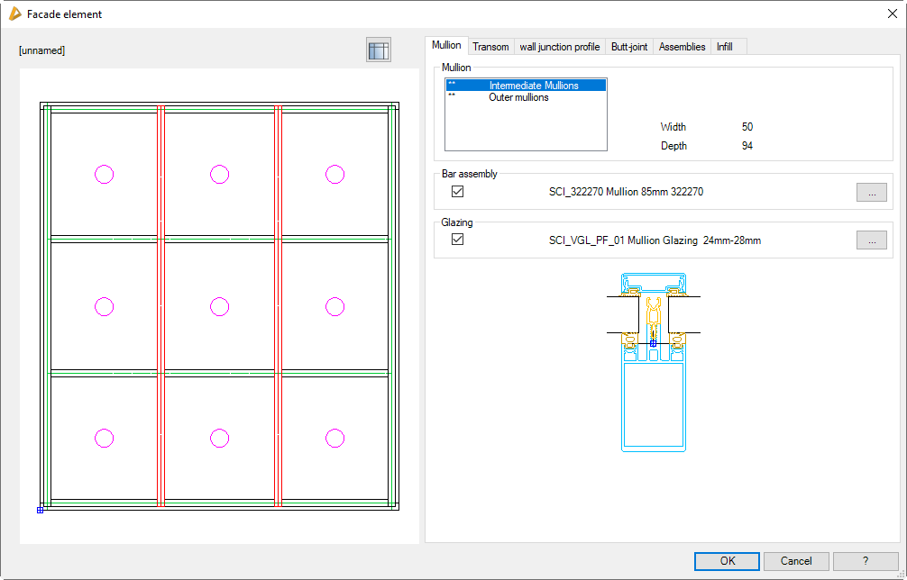
In the dialog box you will find on the left side the display section with the dynamic preview.
On the right side of the dialog box there is the operating section with the tabs:
This changes to the Dialog box Facade element. Here you can define the dimensions, center distances and fields for infills as well as other fundamental properties of the facade element. You will find further information on this in the section Facade element.
On one hand the facade element preview provides a visual check and on the other hand offers further functions:
• Additional functions are activated by clicking in the preview with the mouse wheel. You will find further information on this in the section Object preview.
• Depending on the active elements, selected ones are highlighted in color.
Here, the various types of mullion are listed. Generally, with the facade element a differentiation is made between outer mullions and intermediate mullions. If you have defined mullions with different dimensions in the Facade element, they are also displayed as separate types of mullion and are designated from the left starting with mullion 0.
Here, the various types of transom are listed. Generally, with the facade element a differentiation is made between head transoms, sill transoms and transoms (intermediate transoms). If you have defined transoms with different dimensions in the Facade element, they are also displayed as separate types of transom and are designated from the bottom starting with transom 0.
Opens the Dialog box For object selection, where you can select a bar assembly to assign it to the marked wall junction profile in the facade element.
A preview of the selected bar assembly is displayed in the lower section of the dialog box.
Tab Joint component
db_ath_front+_verbinder
Defines the bar joints of the mullions and transoms in the junctions.
You will find a comprehensive description of the dialog box elements in the chapter Edit bar joint.
Expanded ...
Opens the Dialog box Bar joint, where you can carry out further settings for the bar joint. Here for example, you can assign a butt-joint connector to the joint.
Tab Assemblies
db_ath_front+_baugruppen
Here, you can assign assemblies to the bar assemblies of the facade element (processes or additional components) according to rules.
Bar assemblies
Lists the existing bar assemblies. Here, you can mark a bar assembly to create an assembly arrangement.
Arrangement
Lists existing assembly arrangements. If you click in this field with the right mouse key, a context menu with functions for adding, removing and editing arrangements appears.
Context menu functions:
Add
Creates a new assembly arrangement for the selected bar assembly. In addition the Dialog box Bar joint is opened, where you can define the rules of the arrangement.
Remove
Deletes the marked assembly arrangement of the bar and removes it from the list.
Modify
Modifies the marked assembly arrangement. In addition the Dialog box Bar joint is opened, where you can define the rules of the arrangement.
Tab Infill
db_ath_front+_fuellung
Assigns infills to the bays of the facade element.
This dialog box section is only active if you have defined infills as frame elements in the Facade element.
Dialog box section Infill
Here, the various types of infill are listed. The number of different types depends on the definition in the facade element.
Dialog box section Assignment
Activate the tick box to assign an infill to the marked infill type. To do this, the Dialog box Apply infill is opened.
End of program
OK
Saves the entries and assigns the allocated mullions, transoms, wall junction profiles, joints and infills to the constituent parts of the facade element.
Cancel
Terminates the dialog box without saving the changes.