Tab ATHENA Modeling > Group Output > Assembly diagram
Menu:
Modeling > Analyze > Assembly diagram
Toolbar:
ATH Analyze > Assembly diagram
Command input:
ath_bgr_workshop
Produces diagrams (derivations) of assemblies. You can generate diagrams of selected assemblies or of whole jobs. The diagrams can be inserted into the current drawing or saved as separate drawings (the latter must occur in relation to the job).
When you call the command, you must select a job in the Dialog box Projects. Optionally, you can select individual assemblies by object selection. Job selection is omitted when you call the command from the Project browser. Then the following dialog box will appear:
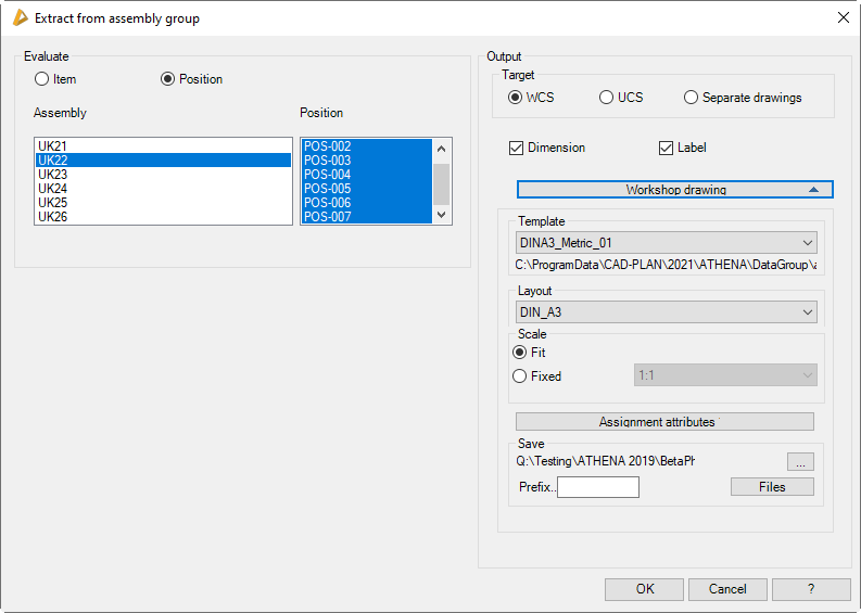
Dialog box Assembly diagram
db_ath_bgr_workshop
Dialog box section Analyze
Item
Generates assembly diagrams by item.
Position
Generates assembly diagrams by position number.
Dialog box section Target
WCS
Produces diagrams in the World Coordinate System (X/Y plane) of the current drawing.
UCS
Produces diagrams inn the User Coordinate System (X/Y plane) of the current drawing.
When you use the options WCS or UCS and terminate the dialog box with OK, you can insert the selected assemblies consecutively into the drawing.
Unit drawing
Produces the diagrams in separate drawings for each assembly. You can carry out settings for the file (name, storage location, etc.) in the Drop-down menu Workshop drawing.
Dimensions
Activates or deactivates the dimensioning of the assembly diagram.
Label
Activates or deactivates the labeling of the assembly diagram.
Drop-down menu Workshop drawing
Dialog box section Template
Displays the template drawings. You can choose the required template from the list.
The complete path for the template drawing is shown below the pick list.
Templates for diagrams can be adapted. You can create and use your own template files. In order to be able to use templates for diagrams, you must keep to the following conventions:
• File name - ath_work_xxx, whereby xxx can be any character string.
Shows available layouts of the selected template. You can choose the required layout from the list.
Dialog box section Scale
Fit
Scales the viewport scale such that the complete assembly diagram is visible.
Fixed
Activates the selection menu for scales where you can define a fixed scale for the viewport scale.
Number of pages
Specifies the page number for the first workshop drawing. The page number can be written in the caption via attribute assignment and is incremented.
Assign attributes
Assigns fixed texts (e.g. job number, editor, file name, etc.) to the attributes of the single drawings. To do this the Dialog box Assignment of attributes is started.
Dialog box section Save
Specifies the storage location for the workshop drawings. The current storage location is displayed.
[...]
Starts the dialog box Browse for folder. Here you can select the folder in which you want to save the workshop drawings.
Prefix
Defines the file prefix for the workshop drawings. The file name comprises: the prefix, job designation and part number from the positioning. If no positioning has been carried out, the file name is generated automatically.
Files
Starts the Files dialog box and gives information about the available drawings (*.dwg) of the set folder.
End of program
If you quit the dialog box with OK, the assembly diagrams are generated. If they generate workshop drawings, they are automatically saved. If you insert the assembly diagrams into the WCS or UCS of the drawing, then follows:
Input request
Specify insertion point or: [?]
Use the mouse or enter co-ordinates to specify the insertion point of the diagram.
With the option ? you call the help.
These two queries are repeated until the assemblies have been inserted into the drawing.
Note: This function generates production drawings (diagrams) of assemblies, optionally with additional details. All the data produced are to be checked by the user. CAD-PLAN GmbH can in no way be held liable for the results of this function and any errors and losses arising from it.